Farrell's Blog
Tetris Canopy and a Few Others 
Thursday, June 4, 2009, 08:56 PM
Posted by Administrator
Time for a new post :) I have been busy airbrushing recently and here is what I have come up with:

My favorite so far, the Tetris canopy. Silver base, candy colors, black and white for tints/shades. Made extensive use of my vinyl cutter, total time including a test panel was around 6 - 7 hours.


The colors on this canopy are all candies on top of a silver base. The red and orange were marbleized, this was my first attempt doing that. I like how it turned out. While not obvious in the photo, the marbleized candy red looks like blood spatter / pooling on concrete!


This canopy was a redo of the smaller 450-size canopy I did a while ago. I added two blue stripes and put an Airtronics logo in the windshield area. I'm thinking the blues don't mix well with the rest of the colors, perhaps reds would have been better...


This last one I painted a little while ago. It was kind of rushed and it too is a redo of a previous canopy I did. The original canopy was also for the Raptor but it died a horrible death when I forgot to check my receiver pack and it flatlined on my fourth flight of the day. On a positive note the canopy was the most expensive piece that got damaged during the "chicken dance" that ensued.


-Farrell
1 comment ( 1 view )   |  permalink   |   ( 2.7 / 6 )
DIY Onboard Glow Heater for ~$25  
Saturday, January 24, 2009, 09:49 PM
Posted by Administrator
For the past few months I have searched for a low-cost onboard glow heater. The cheapest one I could find was around $35 and looked poorly built, while the next step up was nearly $70. I decided to make my own onboard glow heater, here was the criteria:

Did not need to be R/C. I just want one less thing to carry around and charge the night before.
Powers off of a 5-Cell NiMH receiver pack, and should not draw too much current.
Very reliable and simple.

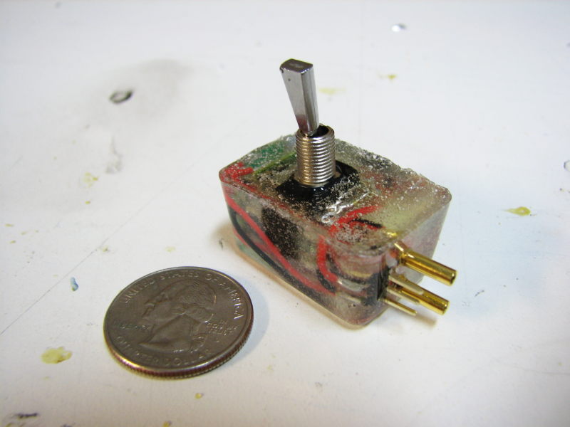
This means you need a simple voltage regulator that will take 6V and drop it down to roughly 1.2V or 1.5V. Add a switch and maybe some lights or a buzzer to alert you when it's on ... and you're done. To make it reliable and fuel resistant I decided to cast my setup in epoxy. Here is what I finally came up with:


There have been three generations of my project. Each generation got progressively better and smaller, with less weight and a neater appearance.

First Generation: Voltage regulator, switch, piezo buzzer, two LEDs with resistors, and output connections. This first one was a complete mess and I did not even bother to take a photo. I wired it very poorly, and put it in a relatively large container. Having used approximately 1 ounce of 30-minute epoxy, when the stuff finally kicked off the thing got over 300F. This significantly melted the plastic container, and the switch failed. The epoxy did not get through the toggle opening, so it must have seeped in from the sides or below.

Second Generation: Voltage regulator, switch, piezo buzzer, one LED with resistors, and output connections. While I only took out one LED, I made this version much more compact and neatly wired. Looking for a smaller container to cast my project in, I settled on the clear dome from the new plastic packaging that Hitec uses with their micro servos. This one turned out perfect, but it still occupied much more space than necessary. I also realized that once a piezo buzzer is cast in epoxy, it gets much quieter :) I covered up the hole in the buzzer so the glue wouldn't harm it, but it just can't produce the noise it does when exposed directly to air.


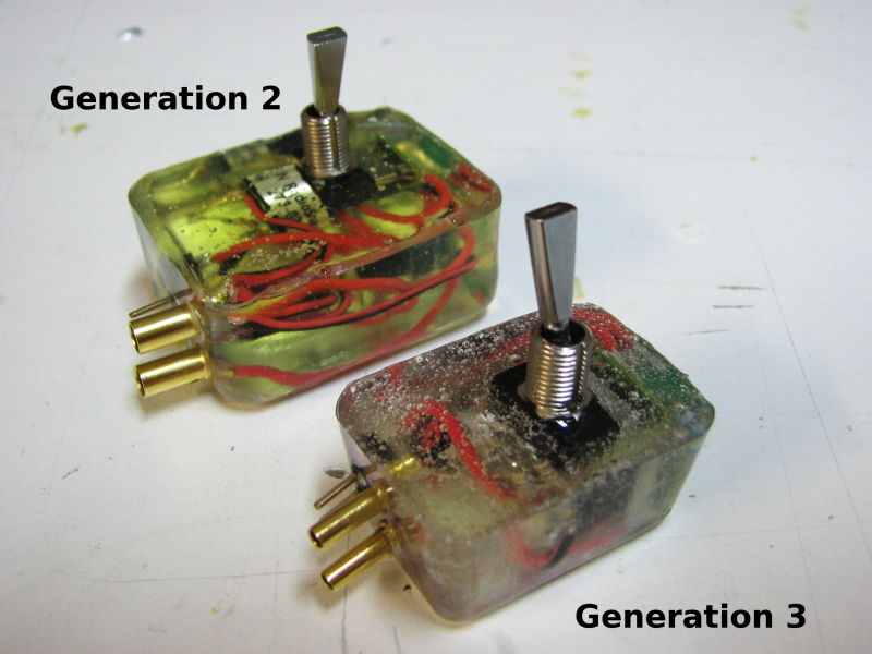
Third Generation: Same as the second generation, but I ditched the buzzer and used two LEDs. This time I found some small blister packaging used to hold crimp-on wire connectors. The packaging was the perfect size, with a small ice cube shape.

-Farrell

add comment ( 1 view )   |  permalink   |   ( 2.8 / 136 )
How to Make an Onboard Glow Heater  
Saturday, January 24, 2009, 01:47 AM
Posted by Administrator


List of Materials:

1x Voltage Regulator: Lineage Power APXS006A0X-SRZ, $12 on Mouser.com
2x Blue LEDs. Lck-Led.com, Under $1
4x 160 ohm resistors. Under $1
1x Package of 2mm banana connectors. Mpi #2854, $3
1x Toggle Switch. $3
Random stuff: servo connector, servo extension, epoxy, CA and blister packaging. I scavenged the glow plug connections from my Hangar9 remote glow setup.


The voltage regulator is the heart of this project. The manufacturer's spec sheet has lots of useful information, it can be downloaded at:

http://www.lineagepower.com/Datasheets. ... heets.aspx

Basically we need to connect the “sense” pad to the “Vout” pad, and connect the “trim” pad and “gnd” pad with a 6.8K ohm resistor. Might as well connect your wires at this time too. I used my Vout wire to connect the sense and Vout pads ... keep things simple.


The sense pad tells the voltage regulator what voltage it sees, and since we are not doing anything complex it just needs to be connected to the Vout pad. The resistor between trim and gnd tells the regulator what voltage you want. A table of common voltages and corresponding resistors is available in the spec sheet, as well as a formula to let you pick an exact voltage. I picked a 6.8K ohm resistor because it was the closest to what we wanted, yielding ~1.3V for the glow plug.

I coated the toggle switch with some black connector coating because my first attempt at the project resulted in a failed switch when epoxy seeped in through the sides or bottom of the switch. Any glue can be used to seal up the switch as long as it has a high viscosity and does not conduct electricity.

Each LED needs a ~300 ohm resistor to limit current. I had a bunch of 160 ohm resistors, so I used two of those for each LED, then wired the two LED assemblies in parallel.


To keep things compact I glued the regulator to one side of the toggle switch with a dot of Shoe Goo, then glued the pair of LEDs to the other side of the switch.


The rest is easy, you just need to connect the wires correctly, and keep it compact whenever possible. Here is a doodle showing the circuit layout... I'm not too good with schematics so bear with me.


Now cut the slot and holes in your blister package to accept the output connections. Slide your creation into the housing, slide the connections into the slot and holes, then seal the openings with a little thick CA or quick curing epoxy. If you skip this step the 30-minute epoxy will seep through. Give it all a final test to ensure it works correctly, then mix up some 30 minute epoxy and pour it in. Try not to cover up the threads of the toggle switch with epoxy, or you will not be able to securely mount it to your model.

Let the epoxy cure, then trim the excess blister packaging with a hobby knife or file. Do the trimming after the epoxy is no longer tacky. If you wait to long, the epoxy will approach a full cure and be hard as a rock.

When you mount the onboard glow heater to your model, I would suggest using a little servo tape to reduce the strain on your toggle switch. Just use the toggle switch nut to keep it secure.

Here is the end result. An earlier version is temporarily hooked up to show the effect.


-Farrell

add comment ( 1 view )   |  permalink   |   ( 2.9 / 112 )

| 1 | 2 | 3 | 4 | 5 | 6 | 7 | Next> Last>>